updated August 25, 2024
WWVB south antenna damaged by severe wind April 6, 2024
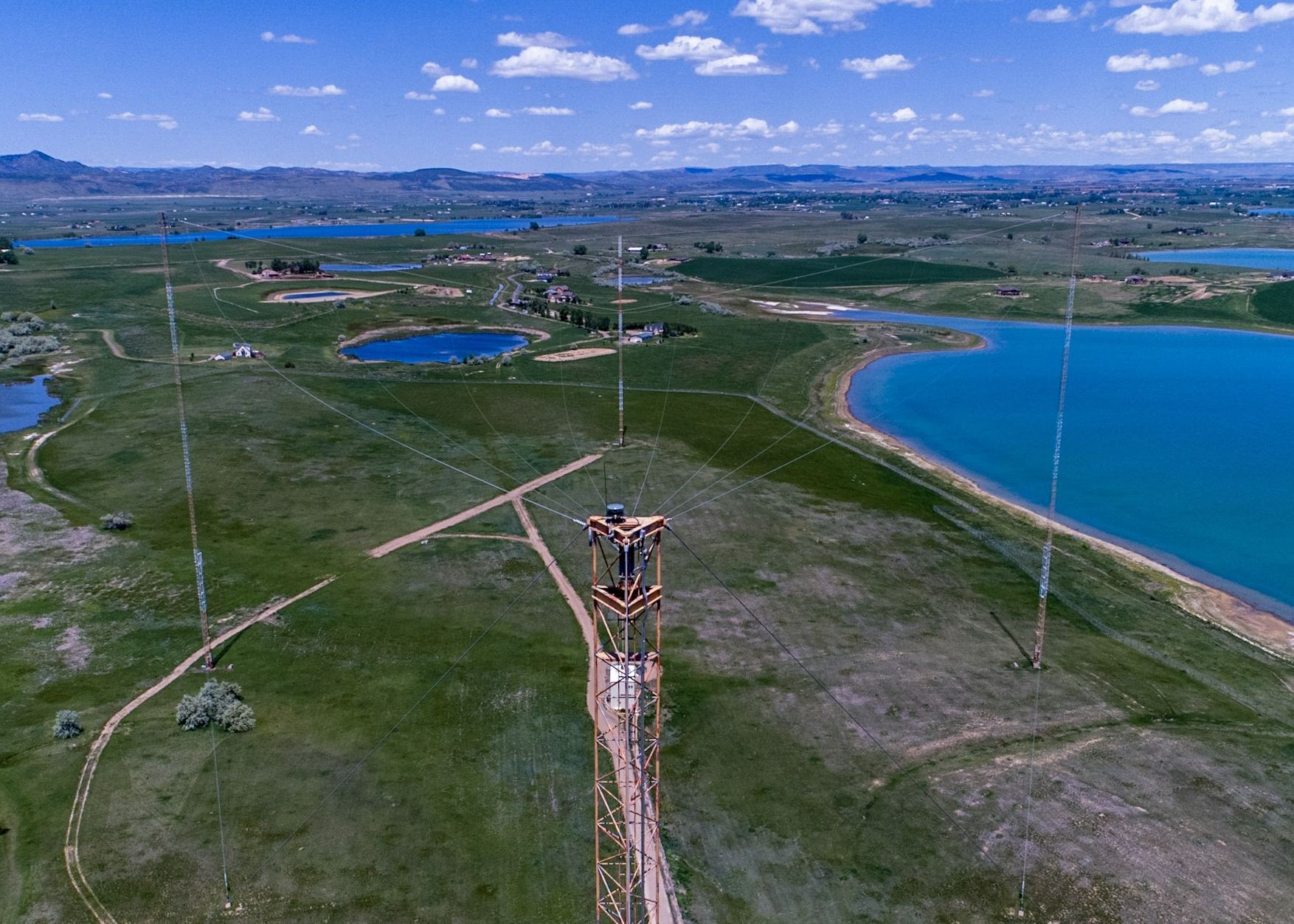
WWVB north antenna top hat - Aerial photo by Dave Winnett, W0DDZ
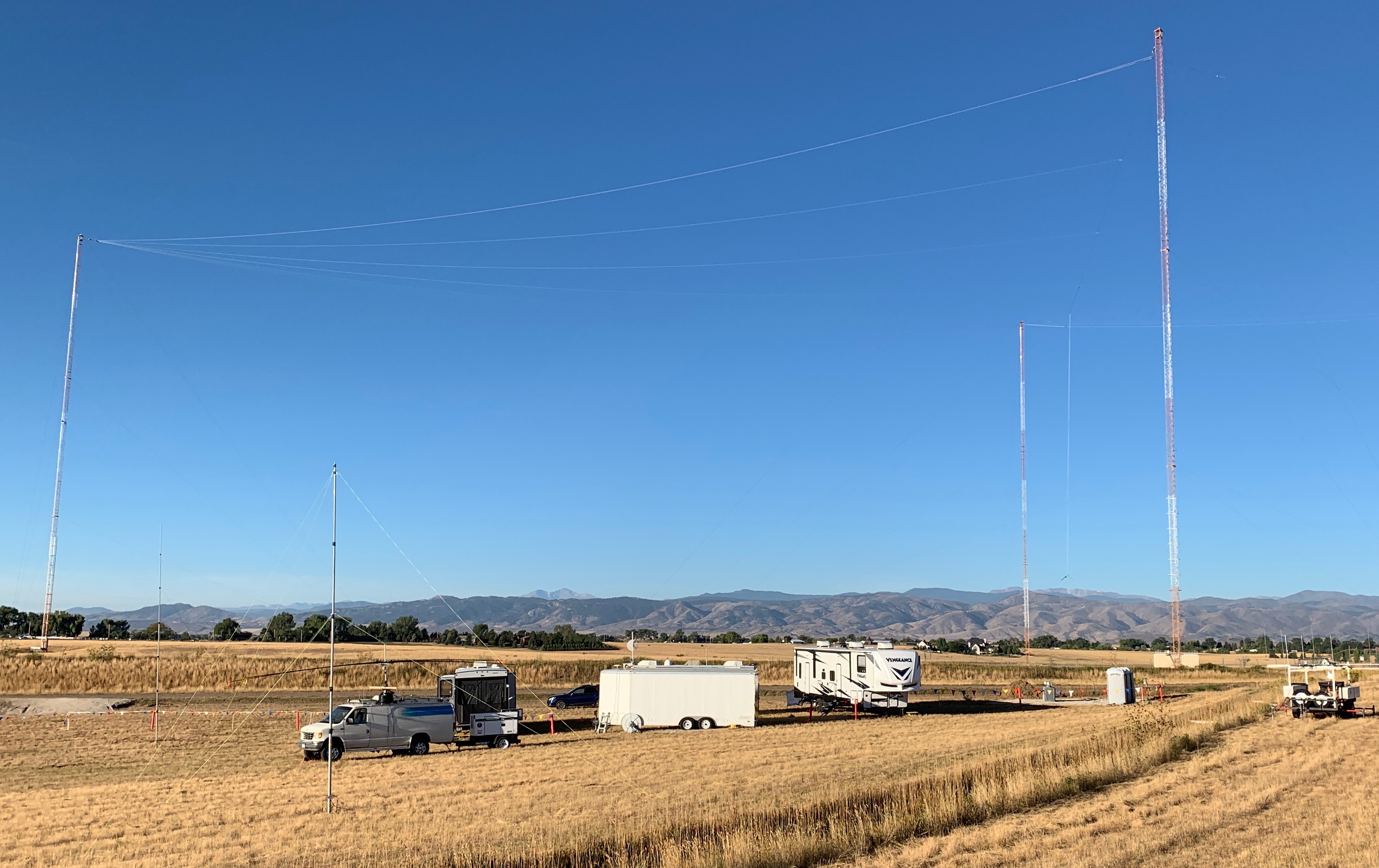
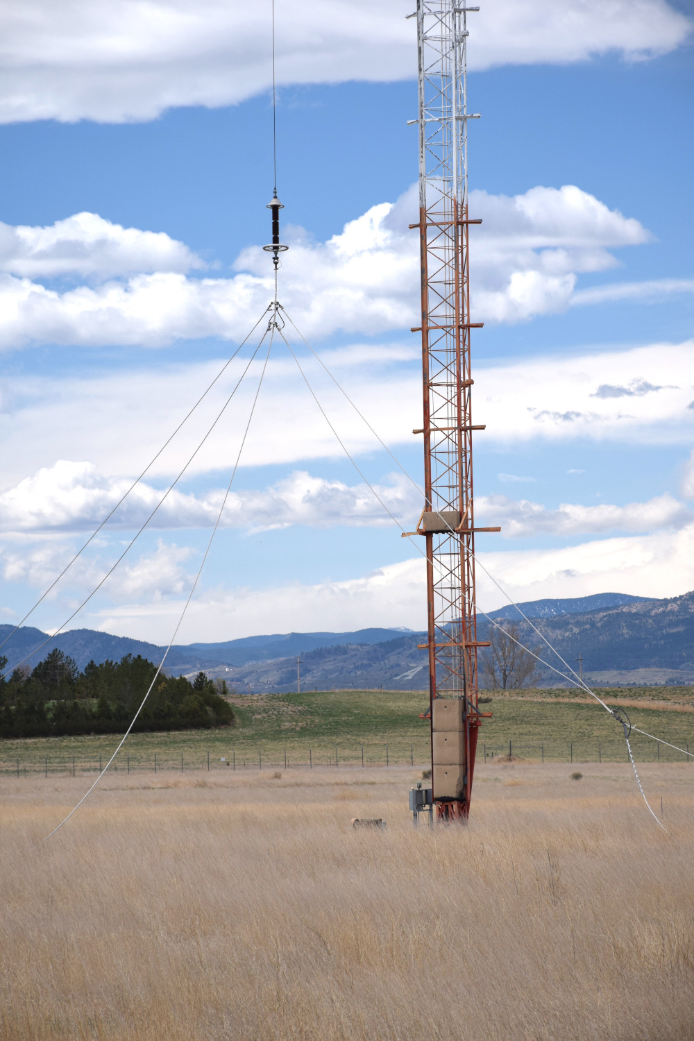
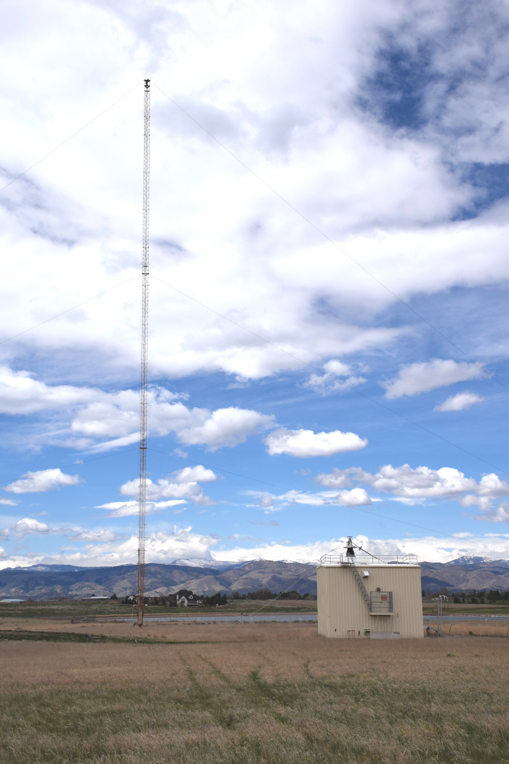
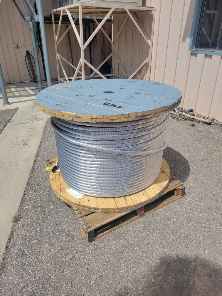
The WW0WWV site in 2019 with WWVB south antenna clearly seen, along with the down lead to the Helix House.
I received an interesting text a few days before our April 2024 meeting from Matt Deutch, N0RGT, Chief Engineer at WWV/WWVB, about damage to the WWVB South Antenna from a major windstorm here on April 6/7, 2024. Wind speeds were clocked locally in the 70mph range, with gusts recorded over 90mph. I-25 in nearby Wellington was shut down in both directions due to overturned semis and blowing debris. The entire Front Range of Colorado was impacted by this severe wind event.
Matt sent along these two photos of the break at Assembly H, tower 4, WWVB South antenna:
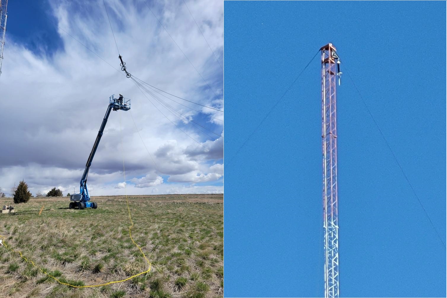
The first image above shows a lift in the process of securing the bridle of tower 3. The second image shows the tower-side of the break in the triatic cable and the isolation insulator.
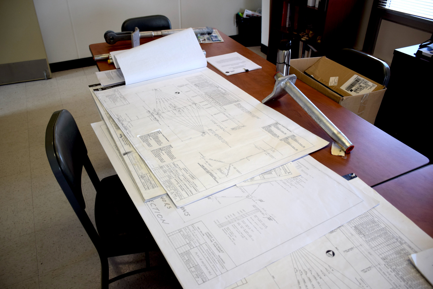
I arranged to go out to the stations on April 26 and found Matt in the WWVB conference room, antenna diagrams as well as a host of spare parts stretched across the table. I spent some time familiarizing myself with the layout of the antenna.
The failure was in the triatic cable, the span that supports the 8 longitudinal runs as well as the down lead to the Helix House, at assembly location H on tower 4 on the south capacitance hat, commonly referred to as a “top hat.”
The term triatic comes from the nautical rigging term for the cable that connects the top of two masts on a sailboat, the traitic stay.
Matt was at the San Diego airport at the time of the failure, so Glenn Nelson, AE0GF, WWV/WWVB Technician, responded to the automated system warning of the south antenna failure. Glenn tried to re-tune the antenna remotely, but when that failed, a visit to the site revealed the break of the triatic cable just at the Assembly H junction, tower 4, with the insulator and descending halyard hanging at the top of the tower.
A benefit of the site visit was perusing the diagrams and getting a better understanding of the antenna design.
The two antennas were originally built in November and December of 1962 for VLF and LF broadcasts. The South antenna was for WWVB at 60kHz, while the North antenna originally broadcast WWVL at 20kHz. The WWVL service was ended in 1972 and the North antenna repurposed in the late 1990’s when WWVB received a significant upgrade. The upgrade improved WWVB performance across the continental US.
According to Matt Deutch, until the wind event April 6/7, 2024, the top hat hadn't been dropped to the ground for 25 years. Most cables and fittings are the originals installed in the winter of 1962.
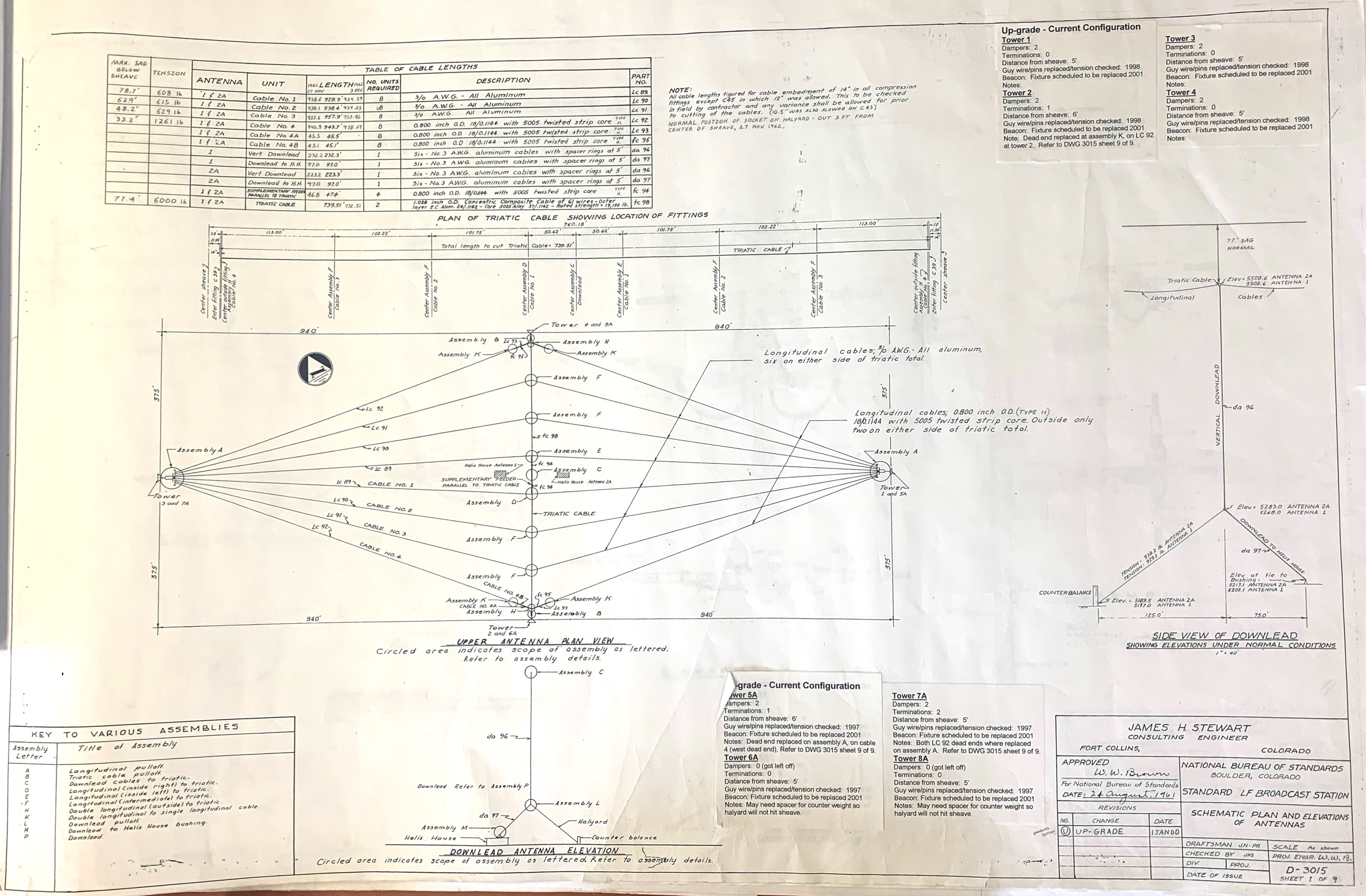
Open the image above in a new browser window and then zoom in on various areas to learn what assemblies are what, cable lengths and tensions, and details on the design.
Here is what NIST has posted about the outage on the WWVB page accessed May 21:
Official Notice: Commencing from 0000 Coordinated Universal Time (UTC) on April 7, 2024, the southern antenna of WWVB has been rendered non-operational due to damage sustained from wind gusts exceeding 90 MPH. Please be advised that WWVB continues to function at a diminished overall power, utilizing only its northern antenna.
Update 20 May 2024: The components necessary for the refurbishment of the southern antenna’s triatic are currently being manufactured and shipped. The projected timeline for the completion of these repairs is tentatively set for the latter part of June 2024. We would like to emphasize that this is an estimated timeline and may be subject to alterations based on a variety of factors. We greatly appreciate your understanding and patience during this process.
NIST radio station WWVB is located on the same site as NIST HF radio station WWV near Fort Collins, Colorado. The WWVB broadcasts are used by millions of people throughout North America to synchronize consumer electronic products like wall clocks, clock radios and wristwatches. In addition, WWVB may be used in other consumer timekeeping applications, such as appliances, cameras, and irrigation controllers, as well as in high level applications such as accurate time synchronization.
The club hopes to have Matt share more details of the plans for the repair at our meeting on May 23, 2024.
Be sure to visit: https://www.nist.gov/pml/time-and-frequency-division/time-distribution/radio-station-wwvb - Great info on everything WWVB, straight from NIST.
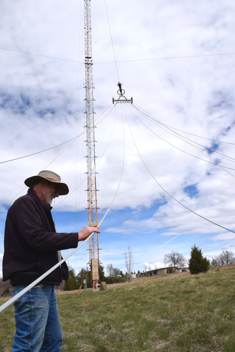
Matt Deutch inspects a longitudinal cable near the lowered bridle of Assembly A.
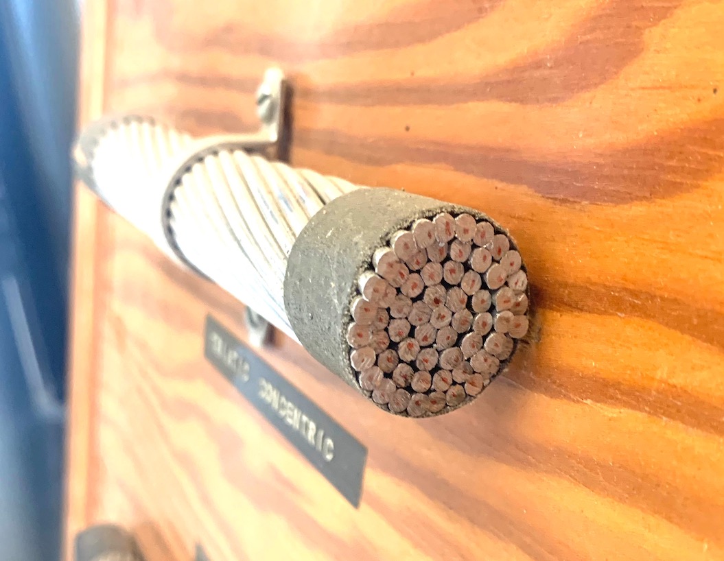
This is what the Assembly H should look like. The Assembly H holds the outer longitudinal cable and the end of the triatic cable. The outer top hat cables develop large voltages and are constructed with a helical core that helps limit arching (see the cable diagram below).
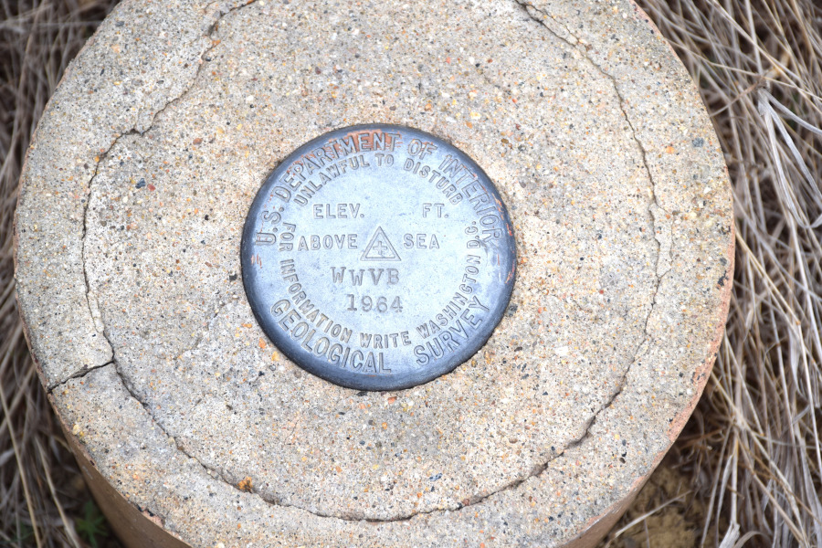
This is the benchmark below the radiating down lead of the south antenna.
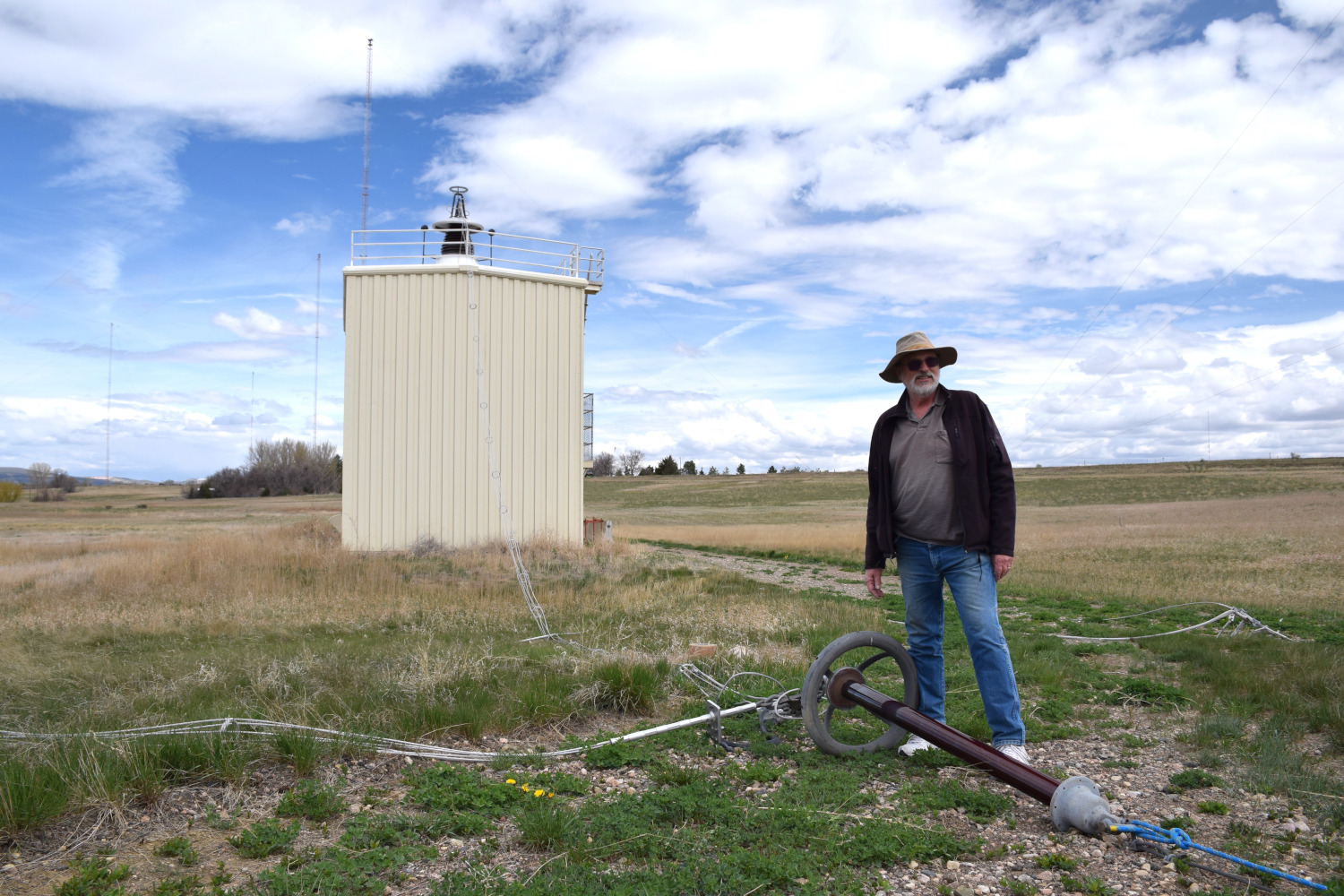
Matt Deutch stands over the insulator that leads to the counterweight holding the down lead vertical and the feed line from the Helix House. See the antenna design diagram (earlier) for the details.
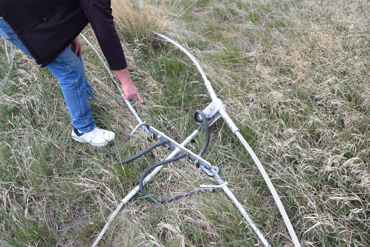
Assembly C attaches the down lead to the triatic cable and the rest of the top hat.
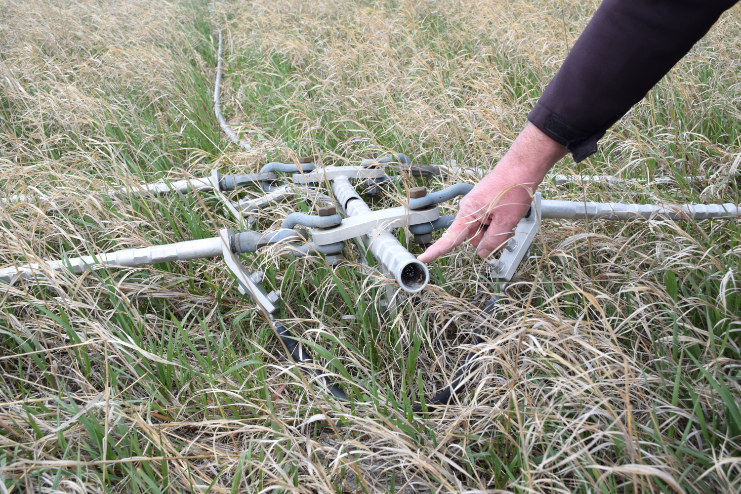
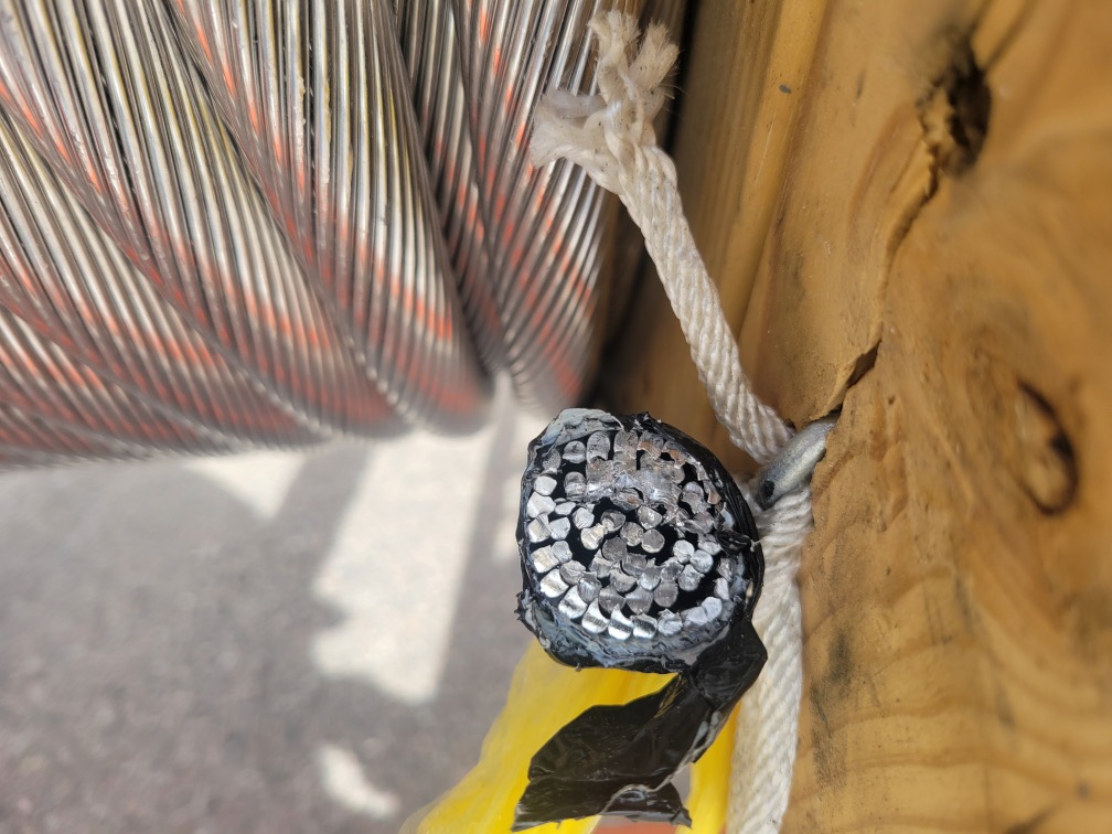
This is the failure point of the triatic cable at Assembly H.
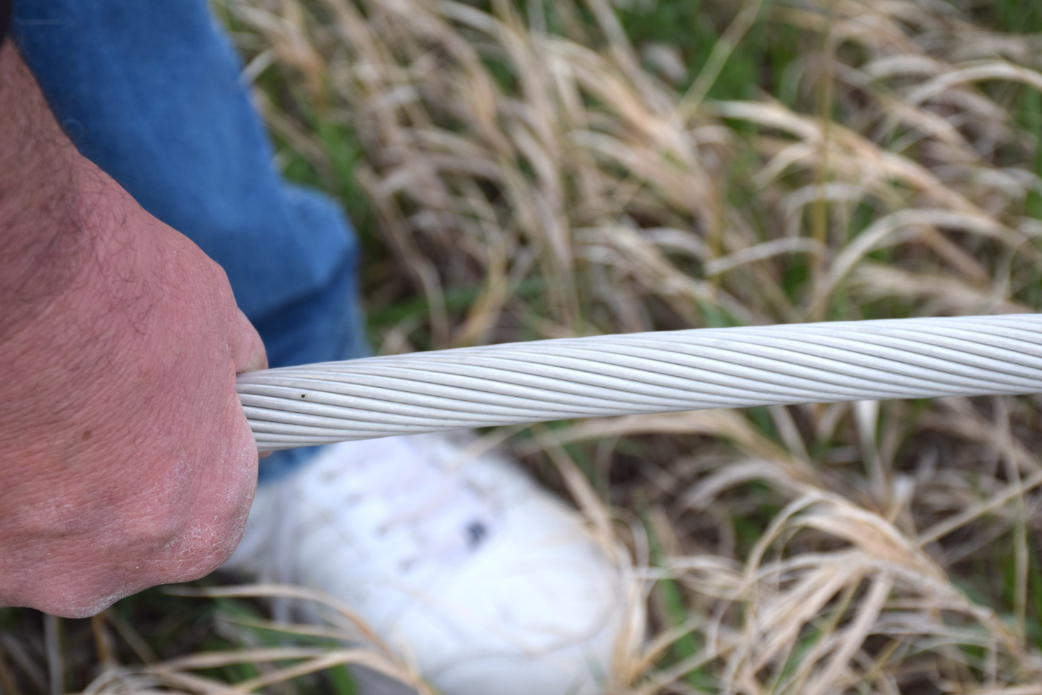
triatic cable
The feed line and down lead lay limp with the top hat lowered. The Helix House contains a large Variometer, a variable inductor, that is used to tune the antenna as physical conditions (temperature, sunlight) are constantly changing.
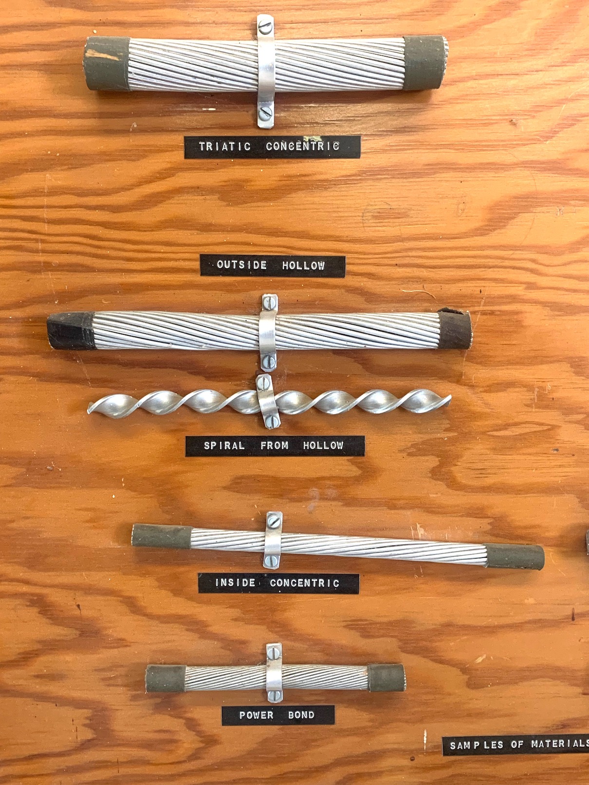
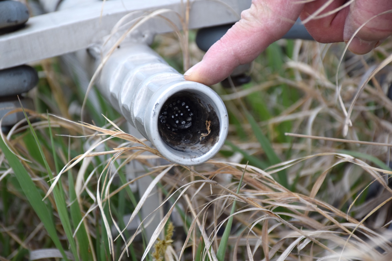
Examples of the cables used in the top hat. The outside hallow, or the "H" wire, has the helical solid aluminum in the core.
The original triatic cable.
The new triatic cable. The inner strands are steel, while the original triatic cable strands were all aluminum.
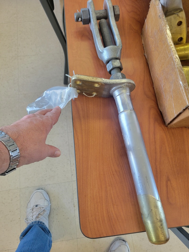
The new "Dead End" which connects the triatic cable to the isolation insulator.
In an updated post on the official WWVB webpage dated July 1, 2024, a hopeful timeline mentions "the later part of September 2024" for repair. In the mean time, the triatic cable has been replaced with new crimps, new power couplings installed, and the antenna essentially ready to raise. Let's hope they can meet their goal so the team can enjoy the 105th of WWV and also the retirement of one of their technicians.
- Dave Swartz, W0DAS, August 25, 2024
Thank you Matt and WWV/WWVB staff sharing the great info and access to the images of the diagrams and the site!
Most photos by Dave Swartz, Matt Deutch provided the last three images of the new cable and parts as well as the two images sent to Dave about the collapse, already credited. WWVB North aerial photo by Dave Winnett, W0DDZ.
Posted by Dave Swartz, May 22, 2024
Updated August 25, 2024